Solar Cables Construction and Specifications
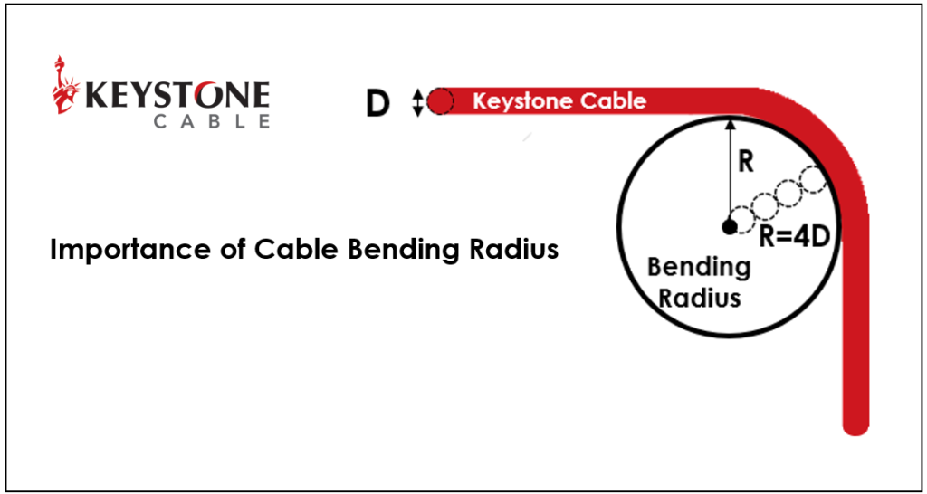
In search of a clean and sustainable energy source for the future, solar remains the most promising renewable energy source for Singapore and most Southeast Asian countries. Singapore aims to harness 1.5 gigawatt-peak (GWp) of solar energy by 2025 and will accelerate the country’s goal to at least 2GWp of solar power by 2030. As a result, there is an increasing demand for Solar PV systems: solar modules, inverters, substructures, plugs, fuses, terminal boxes, and solar cables. In response to the rapidly growing demand of the solar industry, at Keystone, we play our part in contributing to renewable energy sources by providing high-quality Keystone photovoltaic cables that meet stringent requirements. A solar cable is used in photovoltaic power generation. Solar cables are designed to be UV- and weather-resistant and can be used within a wide temperature range for indoor and outdoor applications. Solar Cable Construction Keystone solar cables are double-insulated with cross-linked polyolefin (XLPO). Compared to common power cable insulations such as PVC and XLPE, XLPO has a higher nominal temperature rating of -40°C to 120°C. XLPO insulation has excellent UV resistance, flame retardancy, chemical resistance, and durability. In addition, XLPO is halogen-free, meaning it will not emit toxic gases when exposed to fire. Using poor-quality solar cables may reduce the lifespan of entire solar PV installations, whereas high-quality solar cables prevent pre-mature ageing processes when installed under appropriate guidelines. To ensure the quality of the solar cables, Keystone solar cables are manufactured in accordance with EN 50618 (H1Z2Z2-K) and certified by TÜV Rheinland. EN 50618:2014 consists of a series of stringent tests for cables used in PV systems, which include electrical properties test, constructional and dimensional test, insulation and sheathing material test, cold impact and cold bending test, ozone resistance test, weather/UV resistance test on the sheath, dynamic penetration test, damp heat test, shrinkage test, vertical flame propagation and smoke test. The entire testing process is extensive to ensure the quality and reliability of the solar cables. Keystone solar cables are reliable for the entire solar PV system lifespan as they have a service life of more than 25 years under normal use with proper installation. Here are some installation tips we have gathered to ensure a good solar cable lifespan: Avoid using installation bundles with many cables, as this could raise the ambient temperature of the cables and cause derating. Avoid having cables completely exposed to the weather and laid haphazardly or transversely. Avoid laying cables in the rain gutter. Pay attention to clamped points or cables that lean over sharp edges to prevent damage to the sheath or insulation. Do adhere to the minimum cable bending radius. For instance, please do not install the solar cables in a tight loop formation, as it would likely exceed the bending radius. As solar cables are important to the entire PV system, Keystone technical team can help provide professional guidance on choosing the most appropriate solar cables for your installation. Our solar cables have been selected for large solar farms in Singapore, Indonesia and Vietnam, such as Singapore Solar Nova HDB Rooftop solar project(25Mw), JTC Jurong Island Solar Farm in Singapore, Trung Nam Solar Power Plant(200Mw), Tra Vinh Solar Power Plant(95Mw) in Vietnam and Gangga Island Resort and Spa Solar project in Indonesia. To learn more about Keystone’s solar cables, please contact our team. Contact Sales
Solar Cables Construction and Specifications Read More »