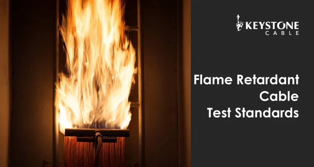
In our previous Keystone Academy blog, ‘What is the Difference Between FRT and FR Cable?’, we shared that Fire Resistant (FR) cables are fire safety products which maintain circuit integrity in the presence of fire, while Flame Retardant (FRT) cables reduce the spread of fire. This is critical so that life-saving electrical installations, such as fire alarms, smoke detectors, PA systems, and emergency lighting, can perform their functions in the event of a fire. Keystone low-smoke, zero-halogen (LSZH) flame retardant (FRT) cables comply with IEC 60332, IEC 60754, and IEC 61034, which ensure that the flame retardant cables reduce flame propagation, prevent the release of toxic gases, and control smoke emission under fire conditions. This article breaks down the standard LSZH FRT test methods in more detail. Flame Propagation Tests: IEC 60332-1-2, IEC 60332-3 Flame retardant cables prevent flame propagation during a fire emergency. The cable’s protective material includes additives such as aluminium hydroxide or magnesium hydroxide. When the material comes into contact with fire, the byproduct from the endothermic reaction is gaseous water which will help envelop the flame and thereby exclude oxygen from the fire. IEC 60332-1-2 is the test for vertical flame propagation for a single insulated wire or cable. During the test, a single-core cable with a length of approx. 0.6m is mounted vertically using two clamps, and a flame is applied to the bottom end for 60 seconds (or 120 seconds if the cable’s overall diameter is >25mm). Passing Criteria: After removing the flame, the burning cable extinguishes itself, and the fire damage is at least 50mm below the upper mounting clamp. IEC 60332-3 tests vertical flame spread of vertically mounted bunched wires or cables. This test is conducted as it cannot be assumed that bunched cables will behave the same way in the fire as single cables. This is because flame propagation along a vertical bunch of cables depends on other factors, such as the volume of combustible material exposed and the geometrical configuration of the cables. Passing Criteria: After the burning ceased, the charred portion does not exceed a height of 2.5 meters. Acid Gas Emission Tests: IEC 60754 When fire comes into contact with polyvinyl chloride (PVC) or other chlorine-containing materials, hydrogen chloride gas is released. Hydrogen chloride gas forms corrosive hydrochloric acid (HCl) on contact with water found in body tissues. This irritates the eyes, mouth, throat, nose, and lungs, thus making escape more difficult. At Keystone Cable, all our fire-resistant and flame-retardant cables use Low Smoke Zero Halogen (LSZH) compounds to prevent the formation of HCl gases from burning cables. International standard IEC 60754 specifies tests for determining the degree of acidity of gases generated during the combustion of materials from electric cables by measuring the pH and conductivity. Passing Criteria: The weighted pH value is not less than 4.3 when related to 1 litre of water, and the weighted value of conductivity is not more than 10μS/mm when related to 1 litre of water. Smoke Emission Tests: IEC 61034 This test measures the smoke density of electric cables burning under defined conditions. The “3-meter cube test” measures the amount of smoke generated by cables in the event of a fire. The cables are placed in a 3m3 enclosure. A tray containing alcohol is supported above the ground surface to permit air circulation around and beneath the tray. The test pieces (cables or bundles) touched horizontally and centred above the tray. Air circulation will begin, and the alcohol (1 litre) will be ignited. A beam of light is transmitted from one window of the chamber to the opposite window. The light intensity is measured between the light source and the photocell. The test is considered done when there is no decrease in light transmittance for 5 minutes after the fire source has been extinguished or when the test duration reaches 40 minutes. Passing Criteria: The recorded light transmittance is at a minimum 60%, which means the smoke density has a maximum value of 40%. For more information, please contact our team. Contact Sales In our previous Keystone Academy blog, ‘What is the Difference Between FRT and FR Cable?’, we shared that Fire Resistant (FR) cables are fire safety products which maintain circuit integrity in the presence of fire, while Flame Retardant (FRT) cables reduce the spread of fire. This is critical so that life-saving electrical installations, such as fire alarms, smoke detectors, PA systems, and emergency lighting, can perform their functions in the event of a fire. Keystone low-smoke, zero-halogen (LSZH) flame retardant (FRT) cables comply with IEC 60332, IEC 60754, and IEC 61034, which ensure that the flame retardant cables reduce flame propagation, prevent the release of toxic gases, and control smoke emission under fire conditions. This article breaks down the standard LSZH FRT test methods in more detail. Flame Propagation Tests: IEC60332-1-2, IEC60332-3 Flame retardant cables prevent flame propagation during a fire emergency. The cable’s protective material includes additives such as aluminium hydroxide or magnesium hydroxide. When the material comes into contact with fire, the byproduct from the endothermic reaction is gaseous water which will help envelop the flame and thereby exclude oxygen from the fire. IEC 60332-1-2 is the test for vertical flame propagation for a single insulated wire or cable. During the test, a single-core cable with a length of approx. 0.6m is mounted vertically using two clamps, and a flame is applied to the bottom end for 60 seconds (or 120 seconds if the cable’s overall diameter is >25mm). Passing Criteria: After removing the flame, the burning cable extinguishes itself, and the fire damage is at least 50mm below the upper mounting clamp. IEC 60332-3 tests vertical flame spread of vertically-mounted bunched wires or cables. This test is conducted as it cannot be assumed that bunched cables will behave the same way in the fire as single cables. This is because flame propagation along a vertical bunch of cables depends on other factors, such as the volume of combustible material exposed and the geometrical configuration of the cables. Passing Criteria: After the